Homemade Rock Climbing Cam


Nick Crews / June 27, 2021
29 min read • NaN views

Using the tools from the Olin Machine Shop at Colorado College, I machined and fabricated my own rock climbing cam, a near perfect clone of a Black Diamond C4 #4 cam. The entire project was self-motivated and self-directed, and I did almost everything myself, with help from a few people. The final product ended up being nearly the same strength as the commercial version, as we tested with the force sensor that I made.
I was in PC108: Intro to Machining and Fabrication during spring semester of 2016. Each student picked a project and worked on that independently throughout the semester with the supervision of our excellent instructor and machine shop wizard Steve Burt (when I say we throughout this series of articles, I usually mean Steve and I).

I chose to create a rock climbing cam. This interested me because I enjoy rock climbing, I would get to learn more about the physics involved with climbing, and I would get practice working with many machining techniques and equipment. Everything was built from raw materials in the Olin Machine Shop at CC and the Pike's Peak Makerspace, with the exception of the sewn webbing loop at the end of the stem, which was made by Runout Customs in Moab. Some of the equipment and techniques I used were a computer controlled CNC mill to cut out the lobes, a 3D printer to make the trigger, a manual mill to machine out the axle housing, a lathe to turn down the axles and stem casing, a hydraulic press to attach the stem, a TIG welder and torch during an attempt to attach the stem, and various hand tools.
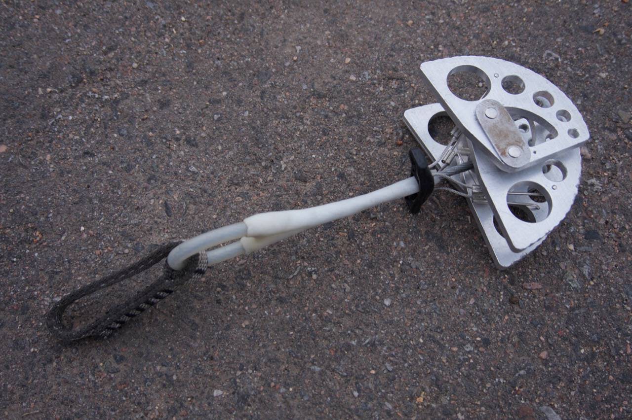
I started work that spring but only actually finished in the fall of 2016. As you can see in the picture above, the final product looked pretty good, almost like something you could buy in a store! So it looks good, but the much more important question is how strong it actually is. I didn't want to use it while actually climbing and trust anyone's life to it. I placed it in a crack and hung my weight on it, so we knew it was that strong, but we needed some way to safely apply a huge load that we could accurately measure. This was the incentive for me to build my force sensor. Using the sensor, we pulled on the cam until it broke at around 14 kilonewtons/3000 lbs, which is the same strength as the real Black Diamond C4 cam!


Table of Contents
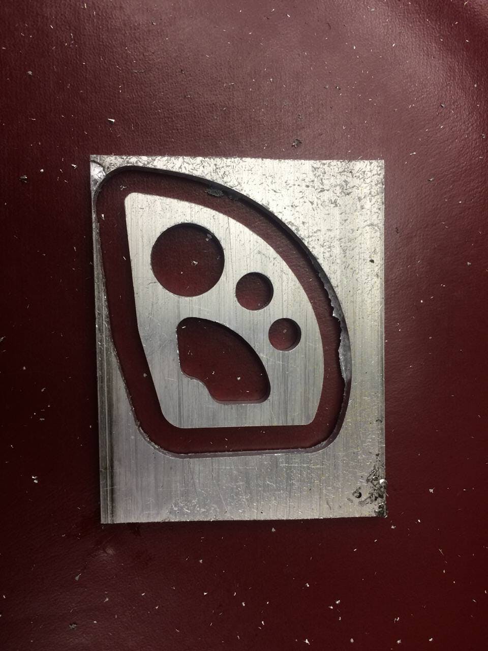
Lobes

Probably the most complicated and time consuming part of the project was making the lobes of the cam. The lobes are super important. If the geometry isn't quite right, they could come sliding out of the rock when you really don't want them too, or they could deform if the load isn't totally in-line as we'd like. The math behind how the lobes of climbing cams work is really cool, and you should read about it here or here. Someone else did some modeling and experimentation here to figure out the stresses in the lobes. After reading the links above, we know that the shape of a cam lobe is a logarithmic spiral, and Black Diamond claims a 'camming angle' of 14.5 degrees. The caliper measurements of the lobe agreed with this 14.5 degree angle, so I went with that.
Now that we can define the edge, how can we actually make this thing? One option would be to use a manual mill. There were a few problems with this though, all stemming from the fact that I would have to move the cutting tool around the part by hand. For one thing, it would be really difficult to get that outside curve on the lobe anything close to exact. Also, I had to make at least 4 lobes, and it would be tough to make very exact copies.
A way around this, and a good excuse to try out some new toys, was to use the CNC machine. It would be able to get the pattern just right, and it would be able to churn out as many copies as we needed.
The first step to using the CNC was to make a computer model of the lobe. I used AutoCAD 2015, installed on some of the school computers, to make the model, based off of the measurements of the real lobe. It took some ancient-greek-style geometry construction to make a logarithmic curve with a camming angle of 14.5 degrees. This is something that I remember from taking geometry class from my mom in 8th grade, so thanks mom! I ignored some of the small details, like the 'scalloping' on the edge of the lobe, and the tiny holes for the springs and trigger wires. These I would add later by hand.
You can view the model below, or download the lobe STL file.
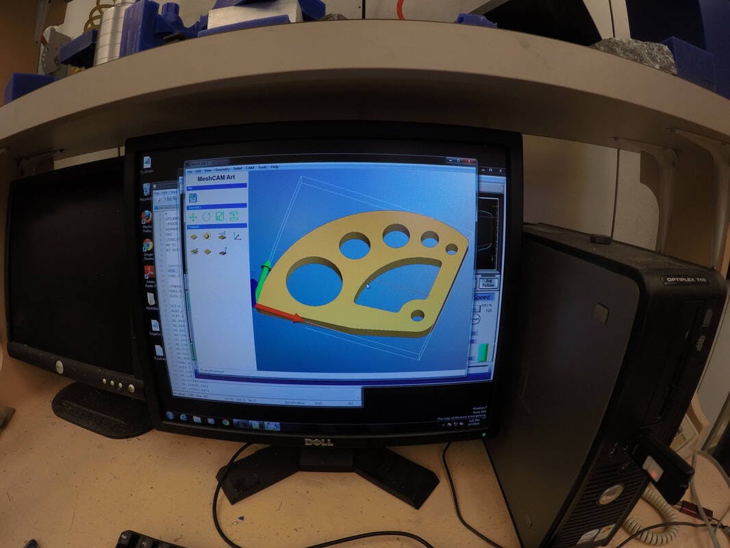
Now, the CNC machine isn't smart enough to understand this 3D model directly. It only understands 'GCode,' which are a sequence of directions like 'move to position (x,y,z)' or 'make a clockwise circle of radius R centered at (x,y,z).' So, I used a program called MeshCAM Art, that transforms the 3D model into GCode. After this, we can feed this GCode into the CNC, and it moves the cutting tool accordingly.
We had a few issues with this process. First, we had to use a decently large cutting tool (the machining term for drill bit) on the CNC so that we wouldn't break it, since we were going to have to cut a decently large amount of aluminum. That meant the tool was too large in diameter to fit inside the axle hole and the two smallest 'weight saving' holes in the middle of the lobe. We would have to do these later by hand as well. The second issue was that the GCode generated by MeshCAM Art is terribly inefficient, even if it does cut out the model accurately. It has the tool jumping around all over the place, not really following a smooth, fast, or logical path, so it takes about 5 times longer than needed, which would have made each lobe take almost 2 hours to make. I had to go into the GCode manually and move around blocks of instructions so that the thing would finish in a reasonable amount of time.
Below are videos of the CNC working through a lobe. This was one of the earlier runs, and so we had the speed of the tool set really slow, since we weren't sure how fast we could cut through the aluminum with a pretty small cutting tool. Later, we were able to bump the speed up to 4 or 5 times what you see here. Then, each lobe took about 20 minutes to complete. I made 5 altogether, so that I could use the first one, which accidentally got a chunk cut out of the corner, as a test piece for the rest of the process.
Here is a timelapse of the weightsaving holes getting cut out.
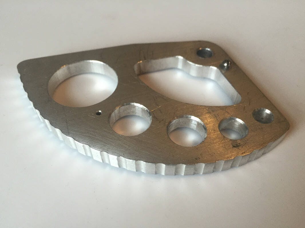
After they were CNC'ed out, I drilled the last 2 'weight-saving' holes and the trigger wire hole by hand, drilled and reamed the axle hole, and drilled and tapped the holes the spring screws would go in. Then I used a rotary table on the manual mill to add the scallop texture around the edge. The result looks pretty awesome, as you can see in the picture at the top of this post.

Trigger
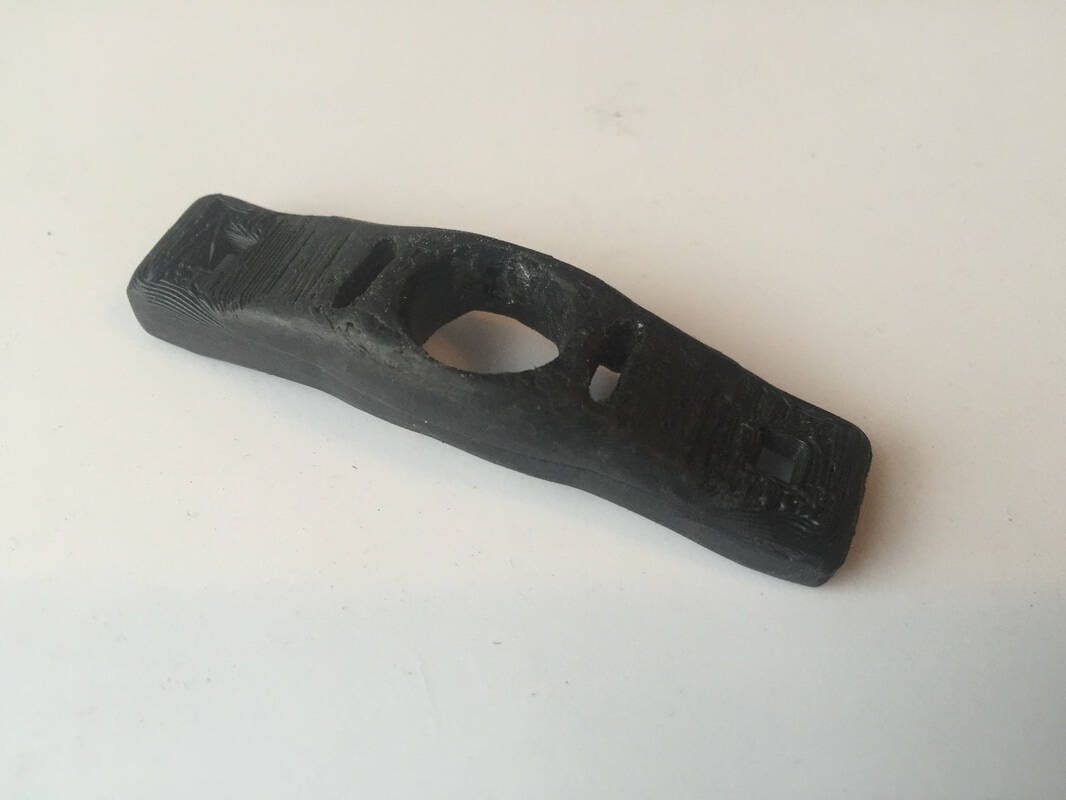
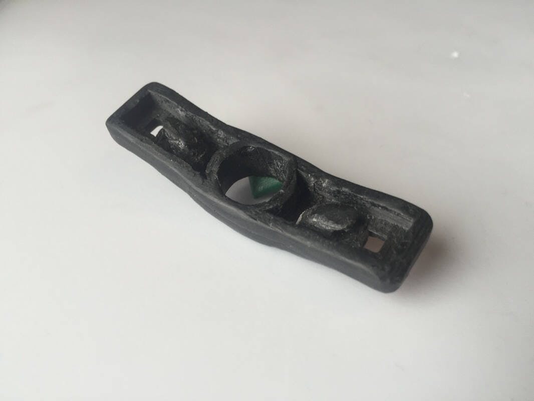
I thought the trigger might be the hardest part of the whole project. It's a really asymmetrical, amorphous shape with lots of little nooks and crannies. That would make it really hard to machine by cutting away material. We thought about trying to make a mold and then casting the plastic, but it would be hard to create the mold by hand, and we would have to make a two-part mold since the trigger has lots of undercuts and details on both sides. We settled on 3D printing since it would be a one step process, and we could design it very accurately on the computer.
At first I tried modeling the trigger from scratch, like I did the lobes. I am by no means an expert with AutoCAD, so I had a much harder time with the amorphous shape of the trigger. Eventually, in frustration, I just googled "rock climbing cam 3d model" with no expectations. Well, hurray for the internet, somebody already did it! I just downloaded the trigger model and used that. It wasn't totally accurate, and was missing the little hooks on the underside that the trigger wires attach too, so after printing I took a soldering iron and some spare plastic and did some manual 3D printing! #artminor. You can view and download the model from the link above.
The CAT lab in the school library has a 3D printer, but it can't do the resolution I wanted. So I turned to the Pikes Peak Makerspace in downtown Colorado Springs. PPM is a really cool organization. From their website: "We are a membership composed of Builders, Tinkerers, Engineers, Artist, Entrepreneurs, Designers, Educators all mashed up and revolutionizing creativity in the Pikes Peak Region. Our goal is to provide a facility with space and equipment for people to create physical items for fun and for education. It also is a place to gather interested people for all manner of classes and instruction." In their workshop they have a full metal and wood shop, a bunch of electronics equipment, a laser cutter, vinyl cutter, and two LulzBot TAZ5 3D printers, all free to use as a member. And through the Innovation@CC program, students can get free membership!
I went over to the workshop one afternoon, and printed out the trigger in less than an hour with help from fellow CS major John Sylvester '18 (He was over there working on his own absurdly cool project, FlyPhone, which leverages the powerful hardware and software of an iPhone to make a cheap, autonomous, personal filming drone!). We used High-Impact Polystyrene (HIPS), which is similar to ABS plastic. We weren't sure what kind of plastic the real trigger was made of, but who cares, our trigger functions the same.
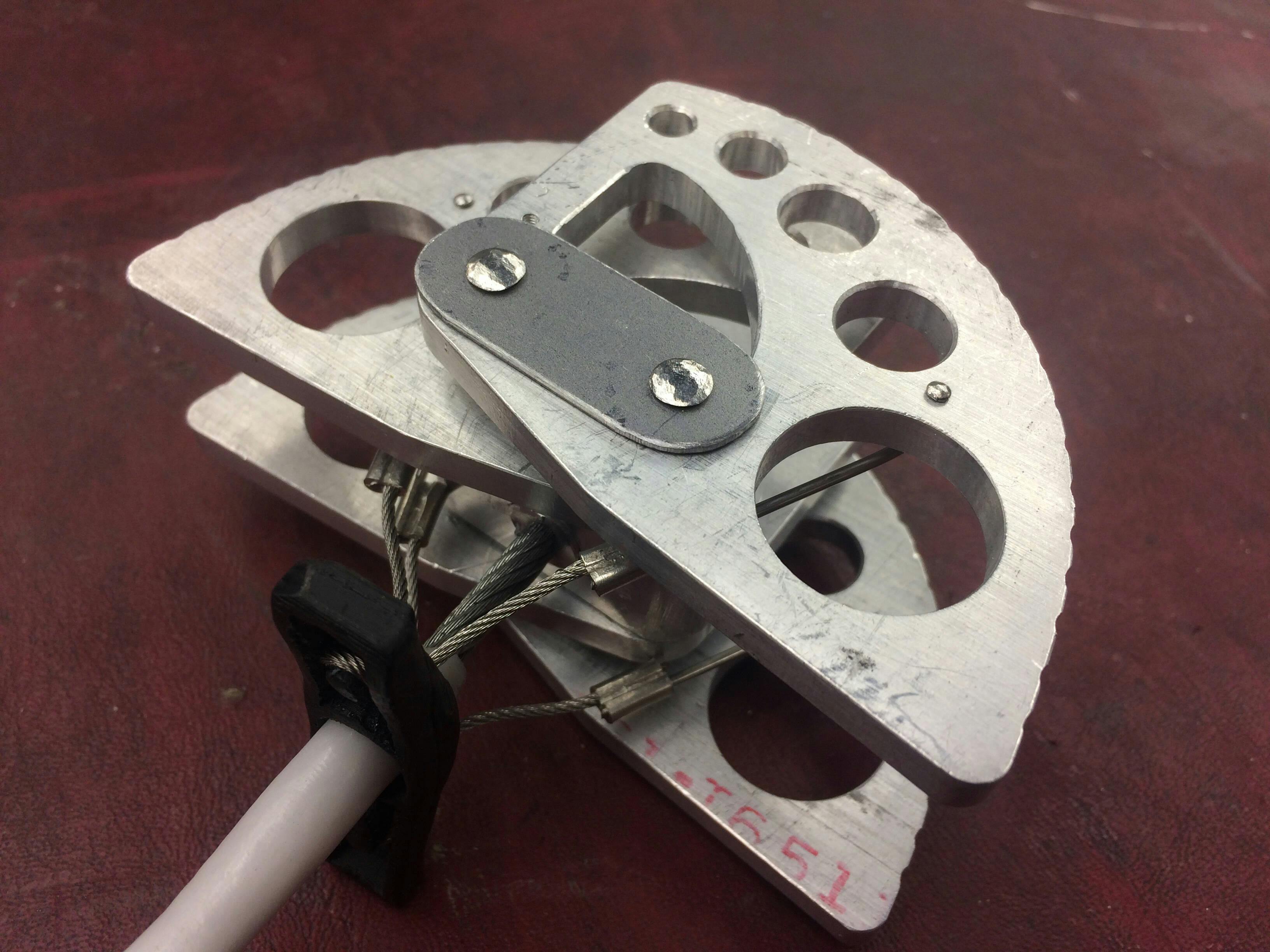
Axles, Axle Plates, and Axle Housing
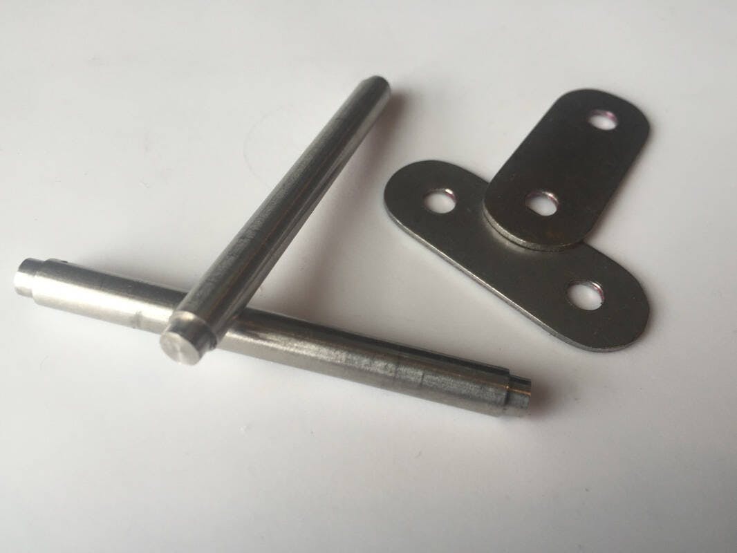
The axles were pretty simple, two rods with some shoulders on either end. Testing with a magnet showed that the real axles were magnetic, and therefore maybe made with some kind of carbon (non-stainless) steel. We guessed that Black Diamond used a medium carbon steel that compromised between strength and ductility, so we went with that. I used the manual lathe to turn down some raw stock.
The axle plates are the flat pieces of stainless steel on the ends of the axles that hold the lobes on. I used the large shop shear to cut out rectangular pieces of stock to the right size, and then used the grinder to round the ends by hand, and then drilled out the holes for the axles.
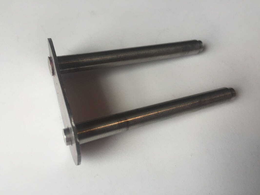
To keep the axle plates attached to the end of the axles, I used a hammer to "peen" (the technical term for "smash", although admittedly slowly and carefully) the ends of the axles into "mushrooms" around the axle plates. This looked to be the same method that the real cam uses, but we guess that instead of a hammer, Black Diamond probably uses a hydraulic press to smoothly and accurately rivet them on. The result looks the same, so hopefully that means it will act the same. This is a fairly important connection, since if the cam is loaded in a crooked orientation, the lobes and axle housing will want to slide down the axles, and the end plates are the only thing keeping it together.
In the above picture you can see one axle before peening, and another one just after peening.
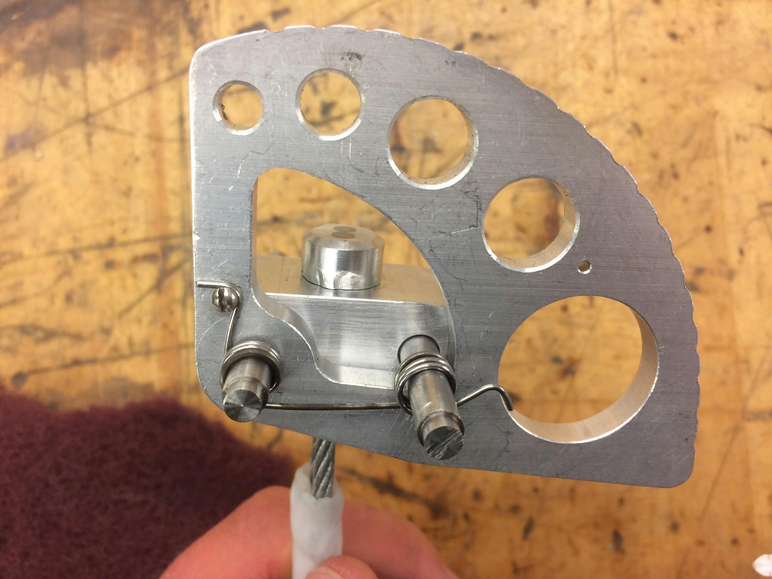
Springs and Trigger Wire
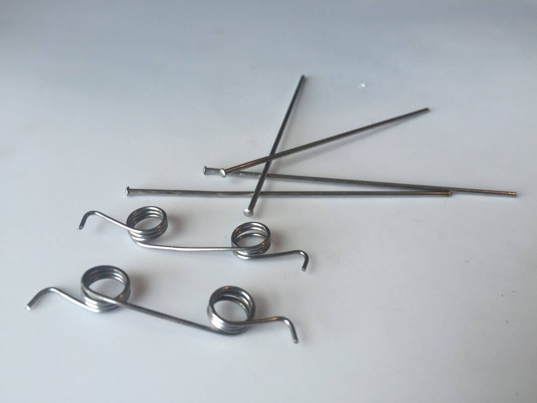
The springs keep the lobes of the cam expanded so that the cam stays in the rock. They are wrapped around the axles and hook onto tiny little machine bolts which are screwed into holes in the lobe. The trigger wires connect between the lobes and the trigger and are used to retract the lobes so that you can fit the cam into a crack. There are two sections: stiff rods (pictured above) that are inserted into the lobes of the cam, and tiny flexible cables that go from these rods to the actual trigger.
For the springs, we had some spring steel wire of the right gauge laying around, so I made a simple form with one of the axles, and just used a pair of vice grips to wrap the spring steel around. It took a little trial and error to get the windings tight and neat, and to get the tension right, but the result behaves just like the real thing.

The first section of the trigger wire, a really thin flexible cable that loops through the hooks on the trigger, we just ordered.
The other part is a stiff rod that threads through the lobe, turns 90 degrees, and attaches to this thin cable. We made this out of some steel welding rod. Where the rod is inserted into the lobe, there is a peened 'mushroom' on the end of the rod that keeps it from backing through the hole. I used a ball-peen hammer to shmush the end of the rod into this shape, and it worked pretty well. For assembly, I stuck the rod through the lobe and bent it into an elbow, locking it into the lobe. Then I squeezed a small crimp around the rod and the cable to join them together.
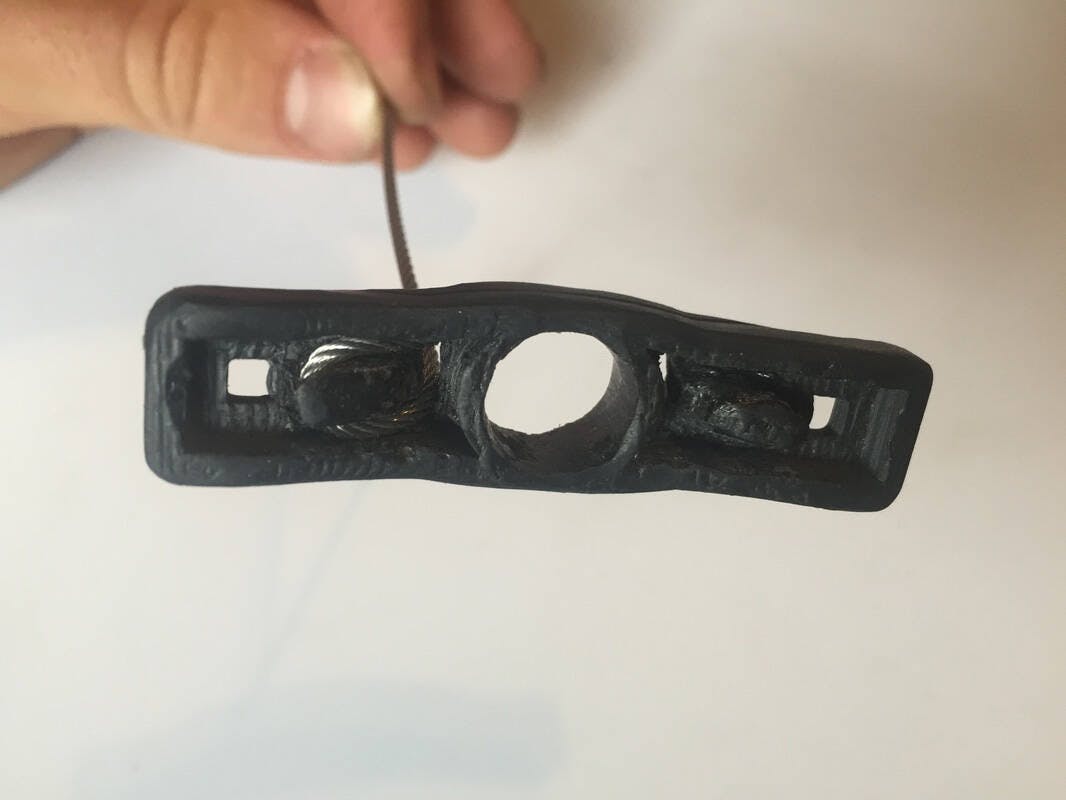
Stem
The stem is the long flexible bit that comes out of the axle housing and ends with a loop and sling to which you can clip carabiners and other climbing equipment. It is the part that you grab onto as you place the cam, and it feels the entire force that is on the cam. This means that it should be comfortable to use, and it needs to be really strong.
We ended up with the same design as a lot of modern cams: a loop of cable swaged together at the axle housing, with a sewn sling at the end to which you can clip carabiners, as well as plastic tubing and molding to make everything sleek and stiff (so the cam doesn't flop around when you grab it by the stem).
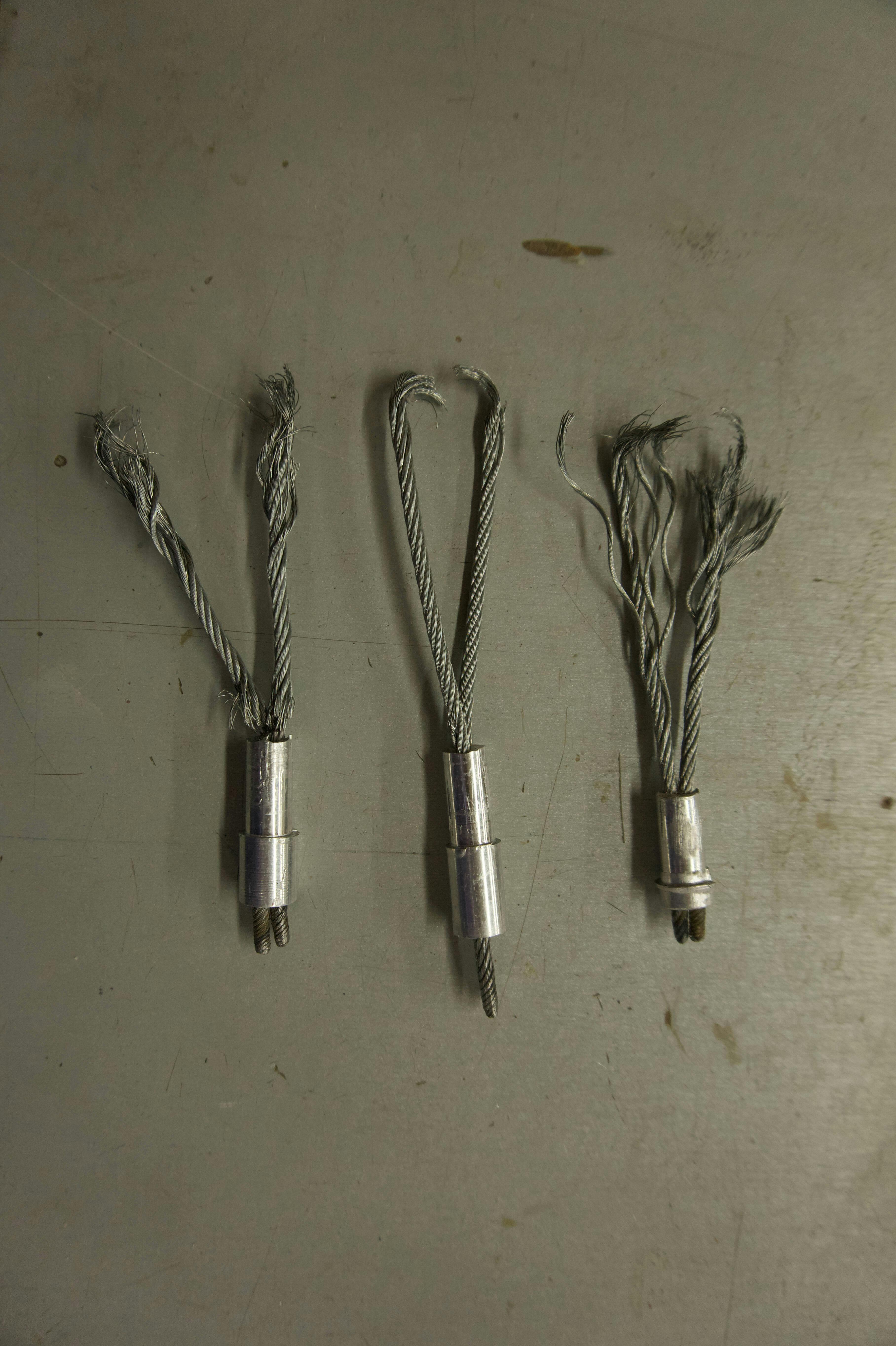
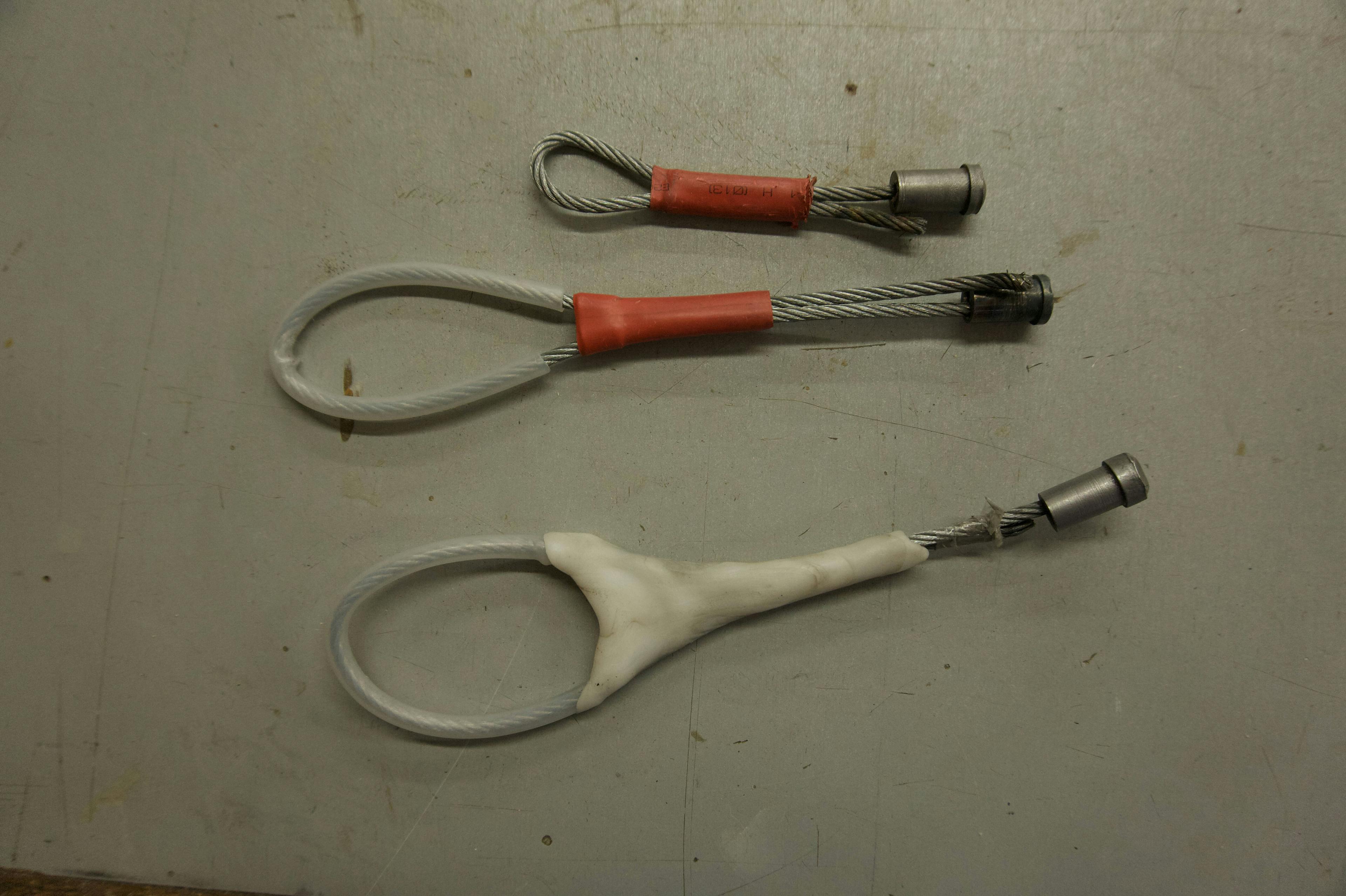
In the picture below is the final design of the swaged stems, after failing from drop-testing, without the molding or any other doodads. Notice that on all the test pieces, the end of the loop broke, not where the cable is swaged into the plug, which speaks to the strength of the swage. In the middle piece, you can just see the severed strand of the cable right next to the plug, where I accidentally nicked it while finishing up the surface on the lathe. Also, the cable ends are much cleaner on the left-most piece because it had plastic tubing around it, while the others didn't.

Below you can see the components of the stem before final assembly.
However, we went through a few different iterations before we got to this design. This is because the stem turned out to be one of the trickier parts of the project, mostly because of the attachment to the axle body. At all the other load bearing joints in the cam (between the axle housing and axles, and between axles and lobes), most of the strength comes from the fact that the two pieces are squarely pushing against each other. Here however, we had to deal with tension as the cable wants to pull out of the axle housing, and this is harder to deal with than the compression forces.
At first we contemplated using the system that climbing nuts use, with a loop of cable threaded around the axle housing. However, there wasn't enough room in the axle housing for the cable to be threaded through twice, so we never did actually pursue this option.
Next, we tried to weld the cable into the axle housing. This was because we were hesitant to try anything with swaging. Real cam manufacturers have really big hydraulic presses and well made dies (basically a mold that you squeeze stuff into) that we didn't think we could replicate.
Eventually, when welding didn't work, we went back to trying to swage, and it actually worked excellently with the equipment we had! As you can read below, the swaged stem was comparably strong to those of commercial cams!
During the design phase, in order to actually make sure they were strong enough, I drop-tested the welded and swaged stems by dropping heavy weights on them. That process is discussed below.
Welded Stems
Using the lathe, I turned down some stainless steel stock into the cylindrical shape you see above, and then drilled out the two holes for the cable to fit through. We then MIG and torch welded the cables into them. We ended up making three, so that we could test them and get some idea of consistency. The cable we used was some 5/32 galvanized steel 7x7 cable, rated up to 2 thousand pounds, which doubled up should get us in the range of 14kN/3150lbs that the real cam is rated to. I had never welded before, so for these very important welds I asked experienced welder Henry Zecca '16 to help me. Thanks Henry!
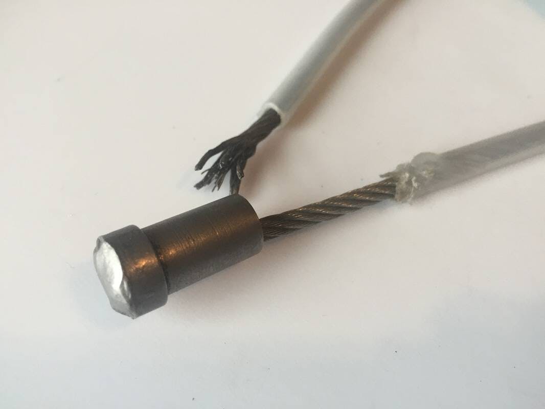
The picture below shows the three initial prototype stems made by welding the cable into the plug. Notice how they all broke right at the cable-weld interface. This is also where we started trying out various options for the plastic tubing and molding.
After drop testing these welded stems (explained below), we found out that this method wouldn't be nearly strong enough. We estimated (extremely roughly) that the welds were breaking at around three to five hundred pounds. Not even in the right order of magnitude!
After discussing, we think we figured out why. We just did welds on the very ends of the cable, where they stuck out the top of the holes in the plug. This meant that there isn't very much surface area of weld, and that the weld is under tension, with the cable pulling directly outwards from the weld. Also, we were worried that the zinc coating of the galvanized cable could have interfered with the bond. Another option is that the heat messed up the temper of the cable somehow, judging from how the end of the broken cable is clean of any welding material, which means the actual cable broke, not the weld. One solution we thought of was to use acid to get rid of the zinc coating, and then cut slits down the side of the plug, and weld up the sides of the cable. Then there would be a much larger area of weld, and it would be under shear load, instead of tension. There would still the issue of the heat changing the temper and weakening the cable, and we would still have to clean up this weld so that it would fit inside the axle housing. In light of these difficulties, we went back to try the swaging method that the real cam used.
Swaged Stems
After the failure of the welded stems, we returned to the swaged connections on the real cam that we were using as a model. On the model cam, there was only one strand of cable, swaged at both the sling and axle housing end. We settled on the double strand though, since it would be stronger, as well as simpler, since it would require only one swage, and there would already be a loop formed for the sling.
This time I made the plugs out of aluminum, not steel, since we wanted the metal to deform around the cable. For swaging, I threaded the two ends of the cable into the plug and then they squeezed the bejeezus (fun fact, autocorrect thinks bejeezus is a real word) out of it using the shop's 5-ton press and some homemade dies, so that the metal of the plug actually flowed around the strands of the cable. These sorts of mechanical attachments are supposed to hold up to 100% of the strength of the cable, so if we did it right this is the best we could ask for.
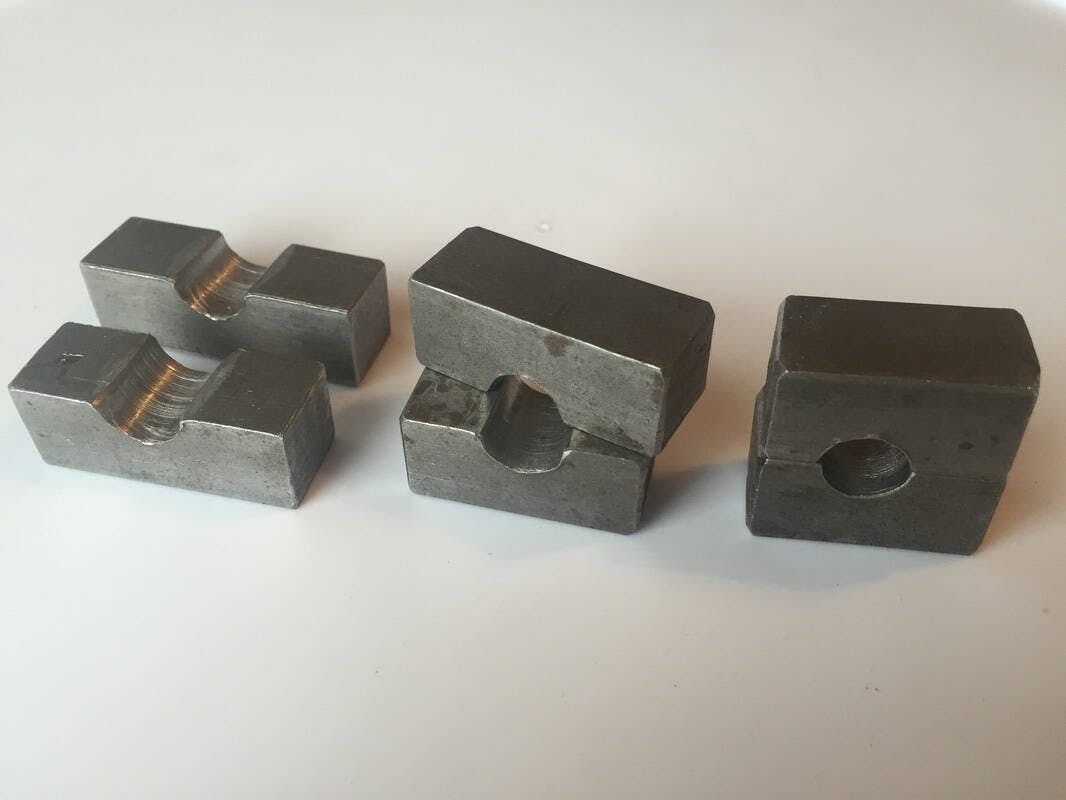
I made the dies out of 5/8 inch steel bar stock. I cut the stock into short lengths, clamped them together in pairs lengthwise, and drilled holes out of the center. I used three different sizes so that the plug would gradually shrink to the final diameter. I found that if you tried to bring down the diameter too much in a single press, the plug would get squished out between the dies, instead of being forced around the cable like I wanted.
To squeeze them, I used the shop's 5-ton hydraulic hand press. Even after using some cutting fluid as a lubricant, the plugs melded with the dies, and I had to give them a nice love tap with a hammer to separate them. Through the sequence of dies, I ended up shrinking the diameter of the plug from 540 to 435 thousandths of an inch. It seemed to work well, with the plug visibly deformed around the cables.
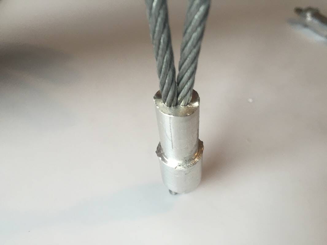
Below, you can see the cable and plug, after swaging and then cleaning up on the lathe. Notice how the plug has deformed around the cables, and as well as the ripply surface of the face of the plug, caused by the stress during squeezing. We decided that in such a small piece, which is also supported by the surrounding axle housing, we didn't need to worry about the piece weakening from this stress.
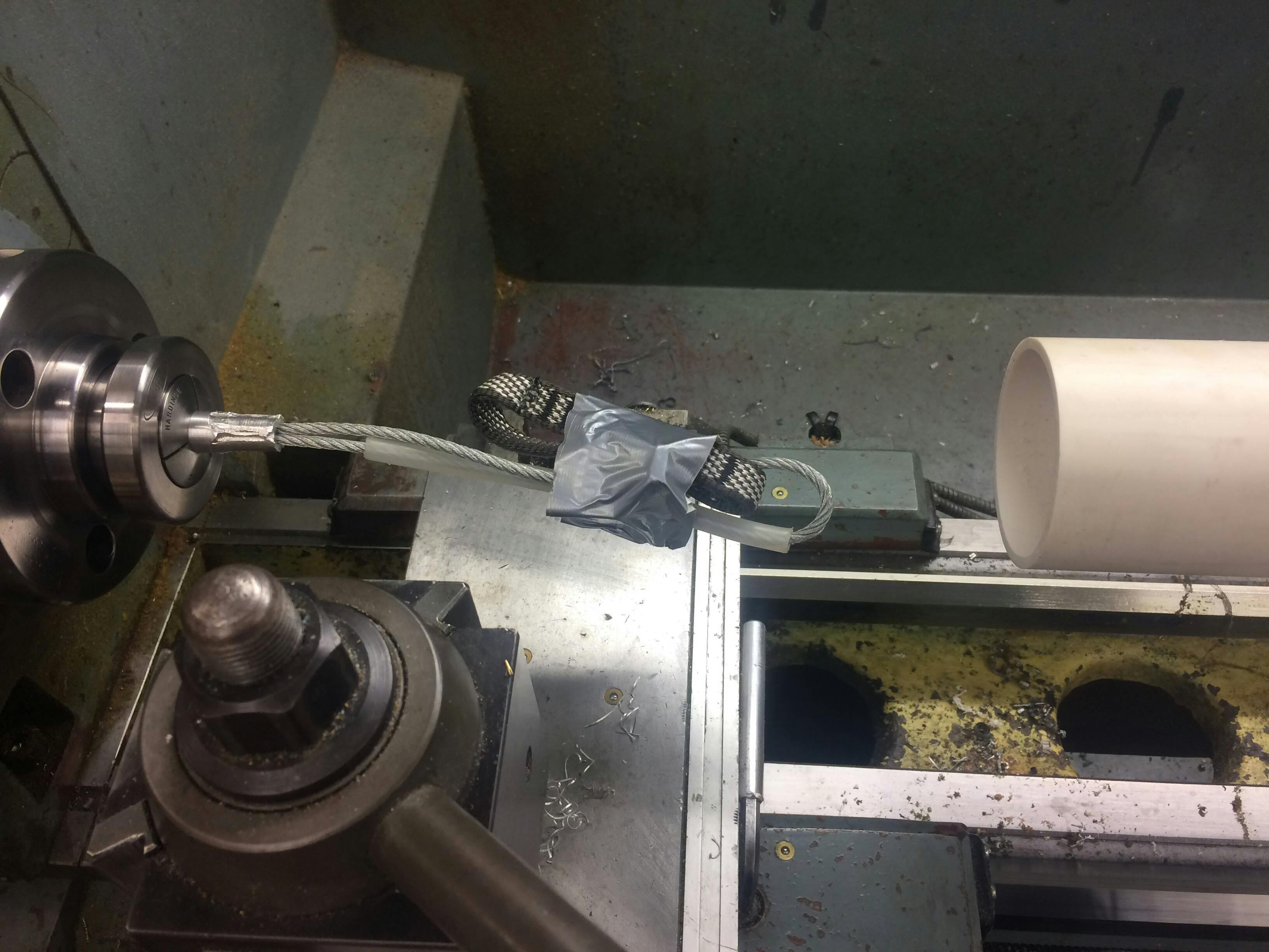
After swaging the cables into the plug, the surface of the plug was rough, and wouldn't fit nicely into the axle body. I made it so the final diameter of the swage was about a hundredth of an inch bigger than the corresponding hole in the axle housing, so there was still some material to work with. I stuck the thick end of the plug in the lathe and worked the diameter down to the final dimension, also leaving a nice smooth surface. The cable, axle housing, sling, and tubing, which had to already be threaded on, spun like some demented whisk in the lathe! This was one of the more funnier and more contrived parts of the entire project as we tried to figure out how to contain the janky looking taped up package.
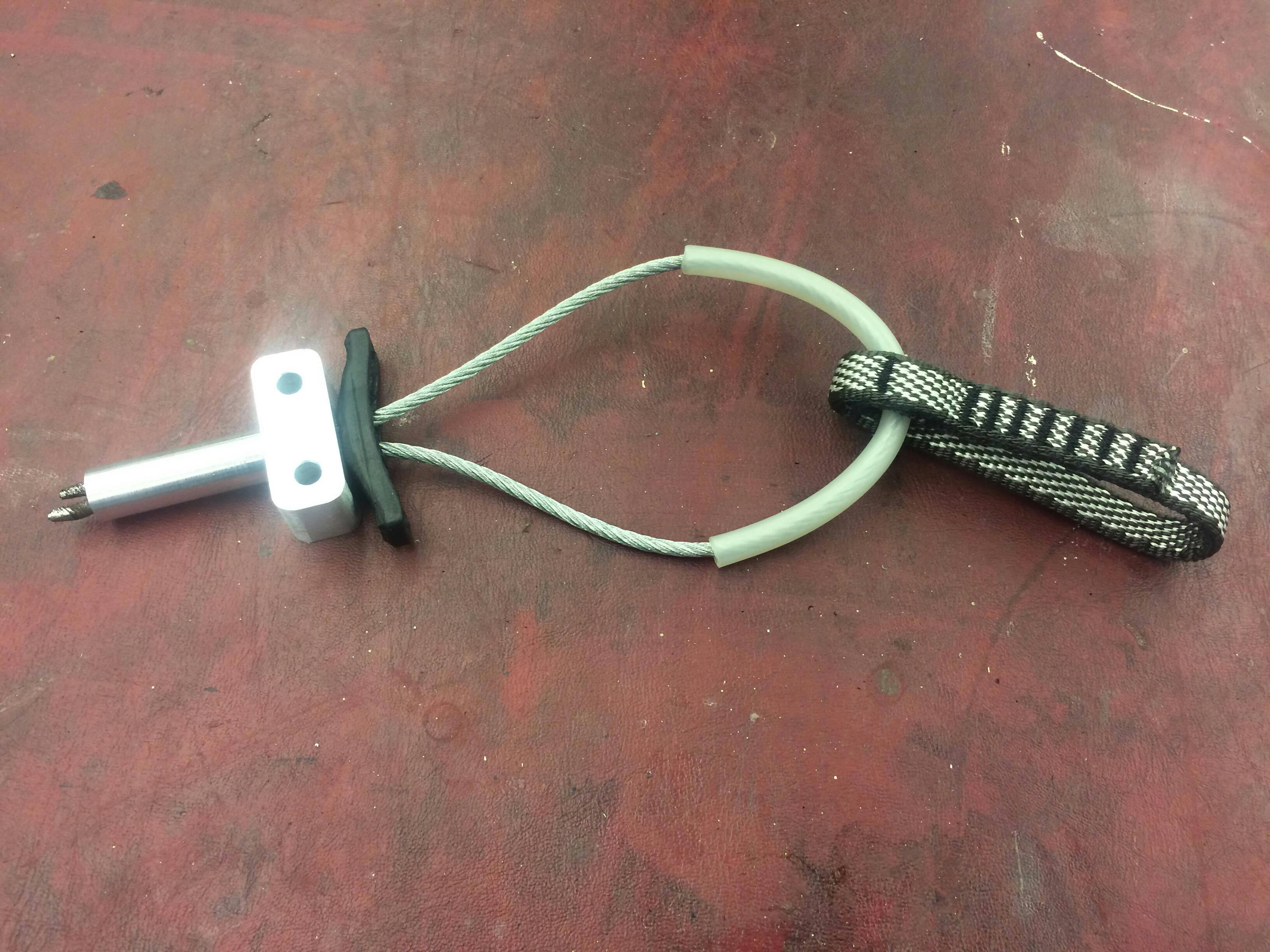
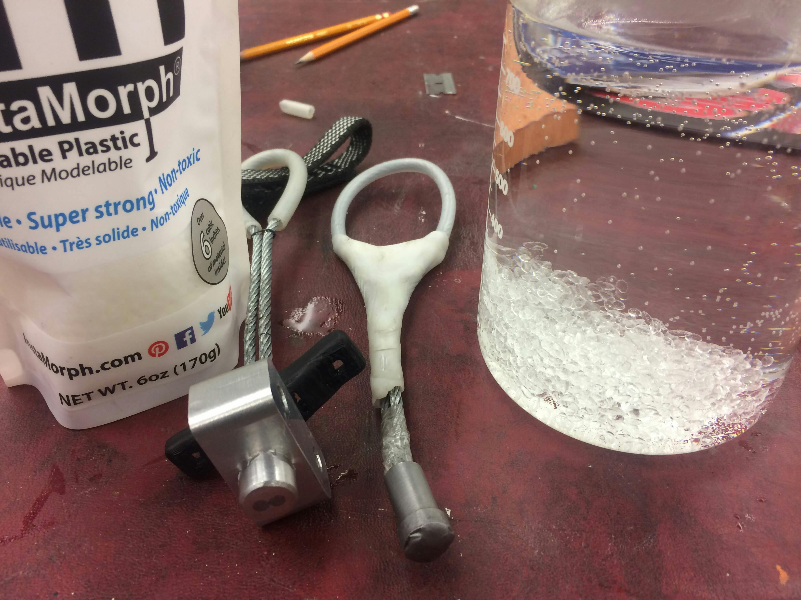
Then, using a mallet, I pounded the plug snugly into the axle housing. Finally, I used this really cool plastic called InstaMorph to make the molding around the stem. When you put it in boiling water it turns into a clay-like consistency that I could mold with my hands, and as it cools it turns into a semi rigid, super tough plastic that is reminiscent of the plastic in milk jugs. It feels exactly like a real climbing cam stem!
In the picture below, the stem on the right was practice, and the one on the left is the final product, ready to go.
These stems did excellently in the testing. Instead of failing at the plug-cable interface like the welded stems, these all failed by the cable breaking at the end of the loop. This implies that I did a good job doing the machining, and we were simply exceeding the inherent strength of the cable. The cable is rated to 2000 pounds, so we figured that the swaged stems could hold at least 3000 pounds, since the cable was doubled up, but maybe not the full 4000 pounds because of the sharp curve in the loop where we clipped the carabiner, which would magnify any stress. For reference, a similarly sized Black Diamond cam is rated to 14 kilonewtons, which is around 3100 pounds.
When we tested the entire cam using my load sensor, the lobes and axles deformed and broke before the stem did at around 14 kN, so our stem did do really well!
Drop Testing the Stems
For testing the stems, I got in touch with Joe Grosjean, mechanical engineer and owner of CityROCK climbing gym. He has a simple drop test setup, on which he has tested many pieces of climbing equipment, including cams. I took the welded and swaged plugs down to CityROCK one Sunday and we put them through the wringer.
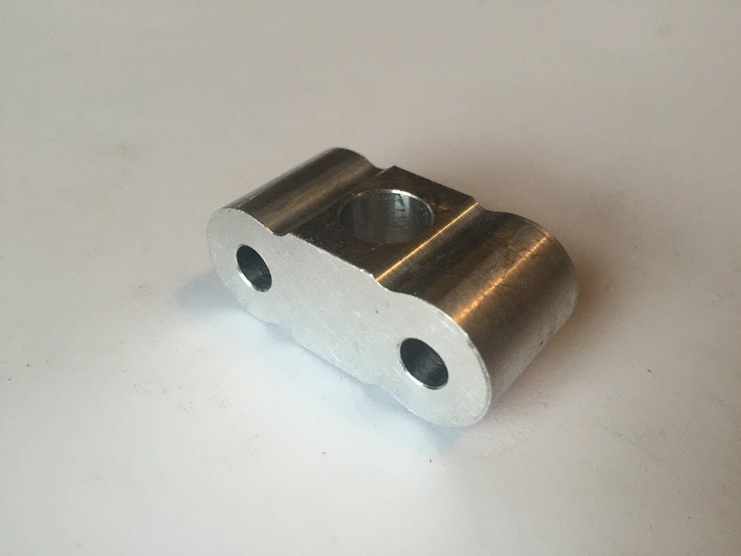
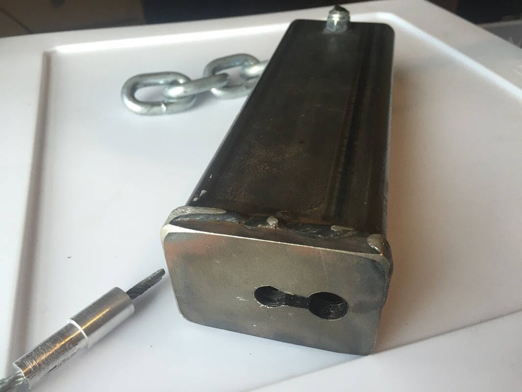
Below is a picture of the testing jig I made. The metal tubing hangs by the chain from the ceiling, and then you insert your plug to test in the keyhole slot on the bottom. This is just like the real axle housing will eventually hold it.
We dropped a 165 pound weight (almost exactly the UIAA standard of 80kg) onto the plugs from some different heights, attached with a chain. Since we used a chain, which doesn't stretch at all, instead of a climbing rope, which is designed to stretch a lot, the deceleration is spread over a much shorter time, resulting in much higher forces for the same amount of drop. Even if the cams wouldn't ever experience these huge shock loads in the real world, we could still get a qualitative sense of how strong the plugs were.
Joe's load cell, which could measure the force on the plugs, was up in Boulder. Despite this, Joe had enough experience with the load cell that he could estimate the force on the plugs just by the sound and way the plugs broke.
Even though we got no real numbers from the tests, we could make some qualitative conclusions: The welds on the welded stems weren't nearly strong enough, and that the swages were working quite well, since the cable was failing before them.
You can see the testing and breaking of the welded stems in the video below. I didn't get any video of the swaged stems, but it looked fairly similar, except we had to drop the weight from higher, and the end of the cable broke instead of the plug-cable interface.
Final Strength Testing
Once the cam was finally assembled, I was very curious how strong it was. In fact, the search to answer this question was the whole motivation for me to make my homemade force sensor.
Once I had the force sensor, I needed an "artificial crack" that would emulate a real crack in the rock. I welded one out of some scramp metal and then used some paving stones as the inner facing material.
Then I wrangled up a few other friends who also are into rock climbing or physics. Watching a cam explode seemed like it would be too good of entertainment not to share with everyone. I'm friends with one of CC's carpenters, Dan Crossey, and he was also psyched. He let us use the parking lot and tools of CC's Maintenance Department.
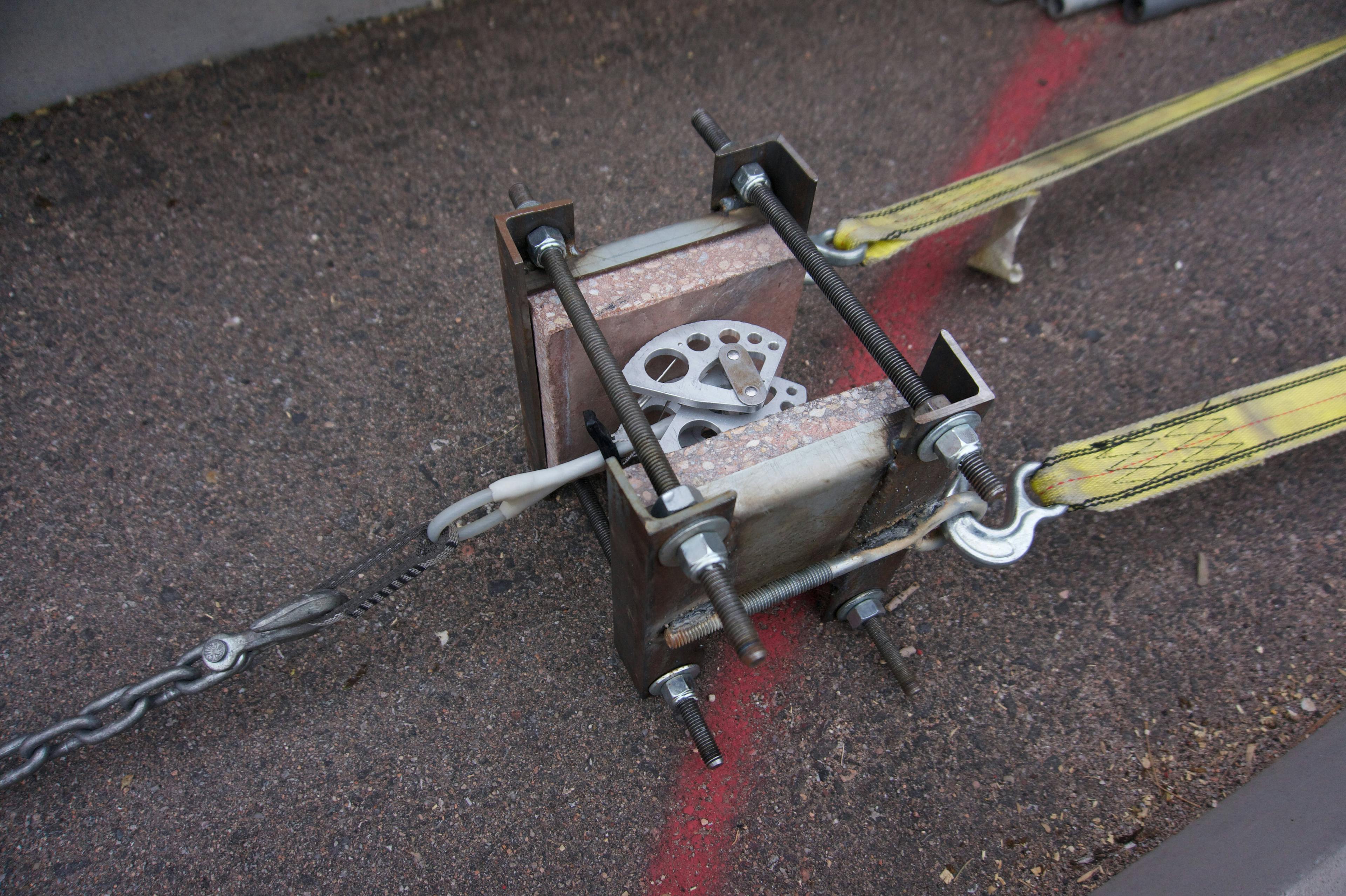
Using some heavy duty chain and tow straps, we stretched the cam, fake crack, and force sensor between two light poles used as anchors. We used a come-along to apply tension.
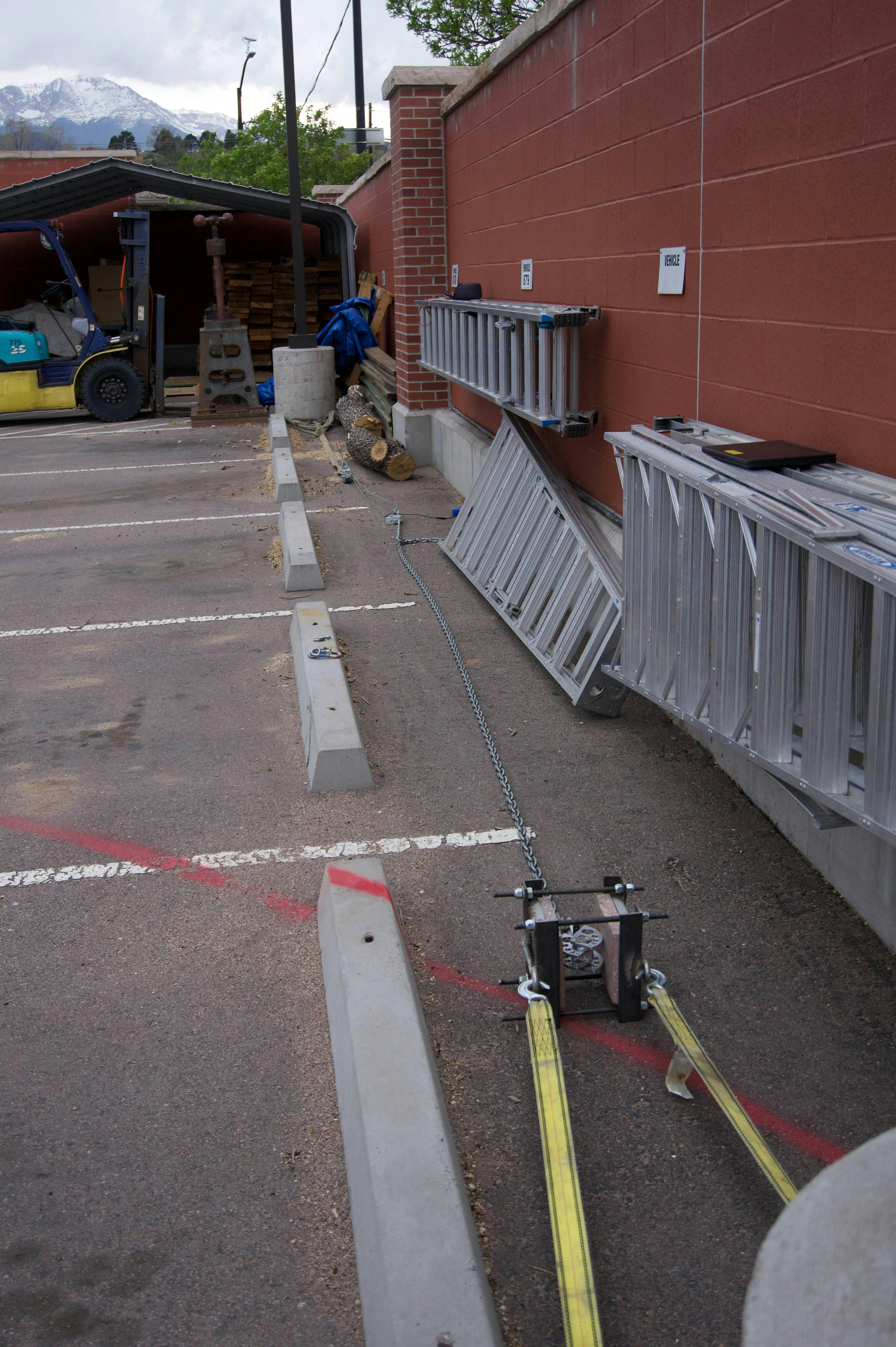
I then hid behind a plywall shield as I started cranking down on the come-along, applying more and more tension to the cam. After very gradually adding tension for about 15 minutes, the cam finally broke. The two timelapses below are at 20x speed, so you can see what's going on.
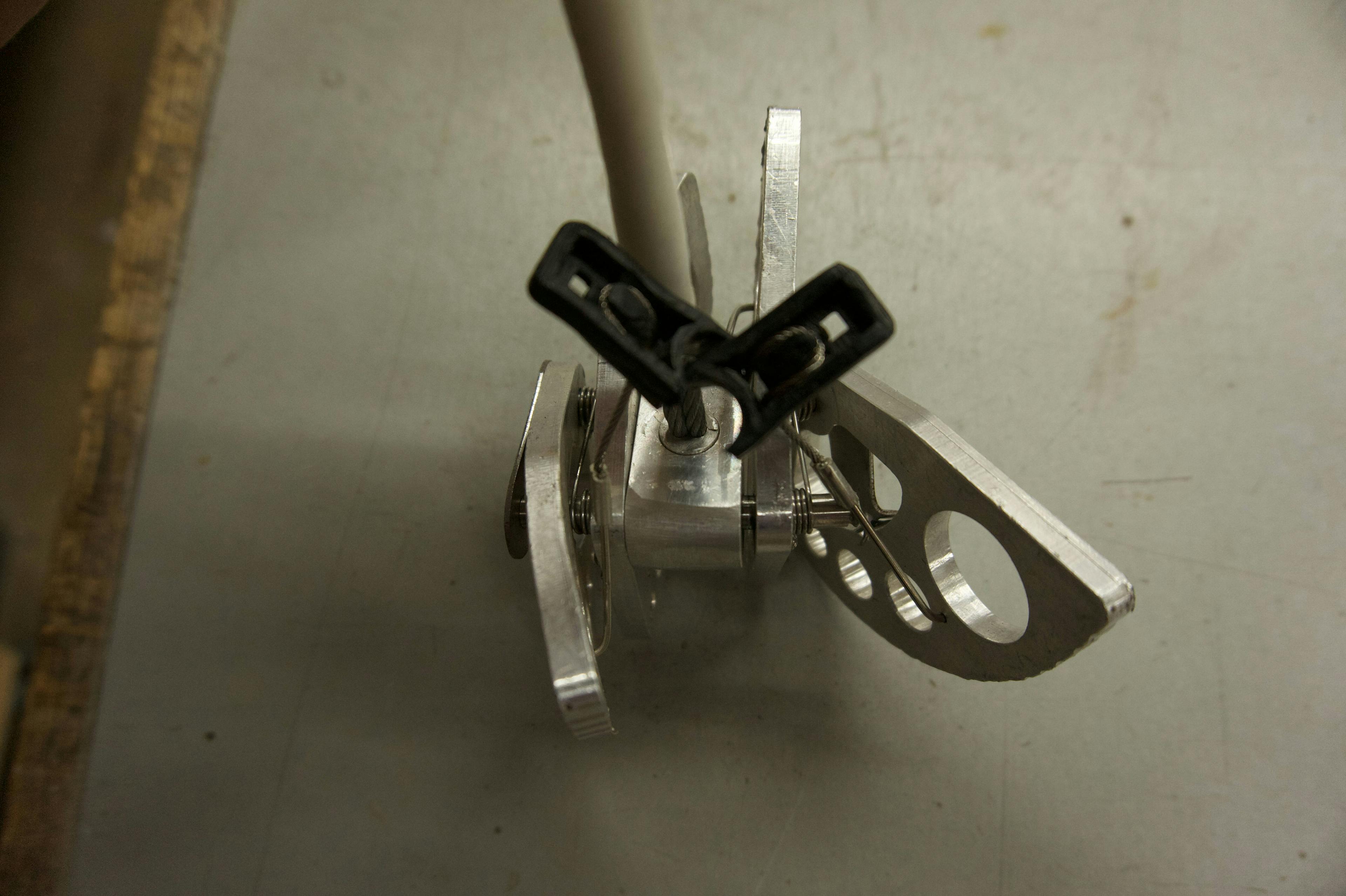
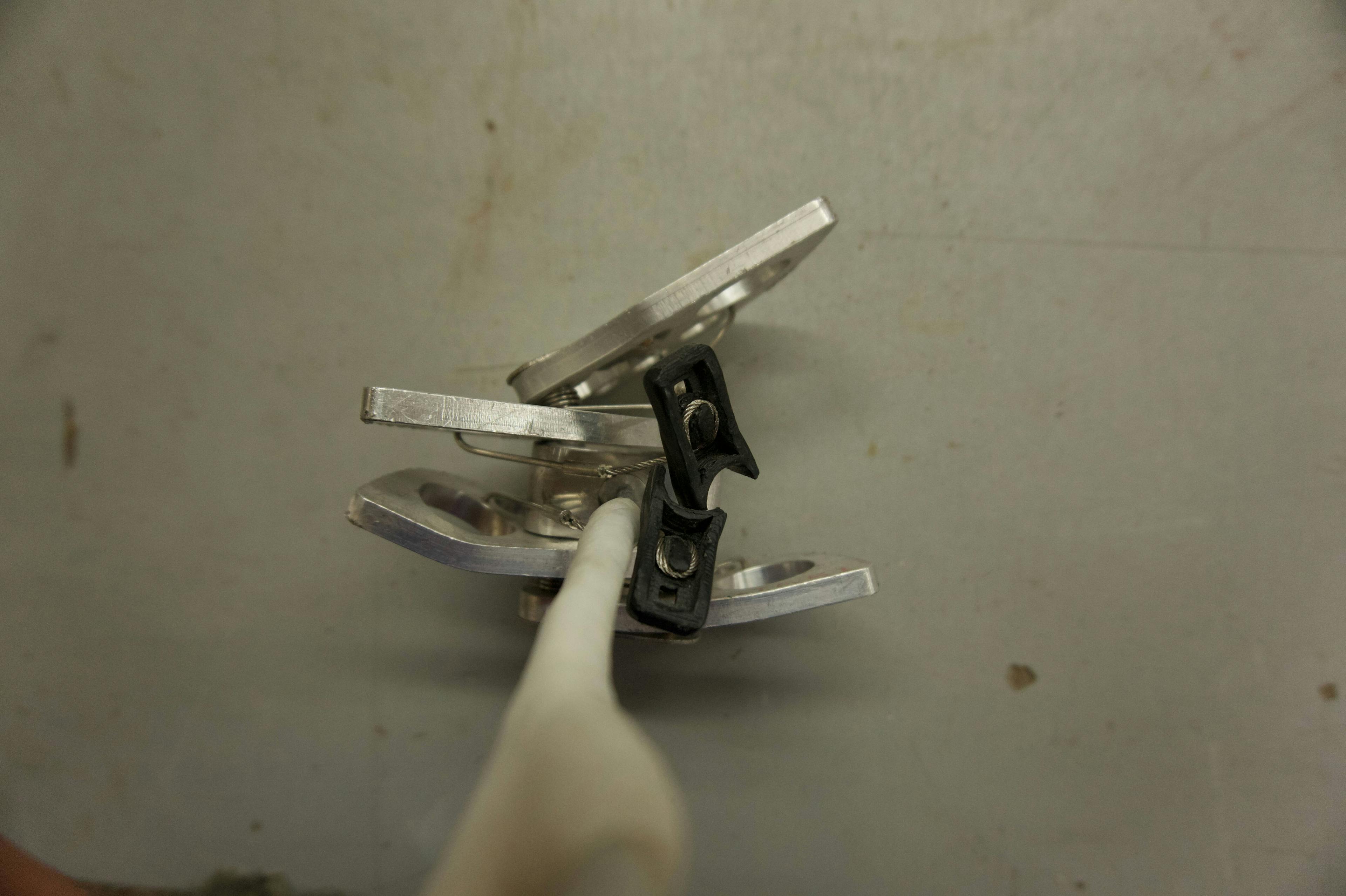
Here is a closeup of the cam as it's tested. Look at how the paving stone cracks, and then towards the end you can see the cam start to bend. It's actually a pretty gripping movie as you hang on the edge of your seat waiting for it to explode.
The test seemed to go pretty well. I recorded the data coming in from the force sensor, and you can see a plot of that below. It goes up in steps that correspond to each time I crank on the come-along. The force declines during rest due to the nylon tow straps slowly stretching.


If my force sensor is to be trusted (and I think it's fairly reliable), then it looks like the cam held up to about 14 kilonewtons. Tha's right on par with what Black Diamond #4 C4 cams are rated to, which is exactly what I was cloning. That's pretty good!
You can see in the pictures below what the cam looks like now, all twisted and busted.
It's interesting to speculate on how the cam failed. Obviously the cable stem and where it is swaged into the cam body didn't fail, which is pretty sweet because that's what I was worried about most. It looks to me as though the loading wasn't quite even, and that started bending some lobes. As soon as that pressure was out of alignment, it just got easier and easier for that piece to continue failing.
I think what this demonstrates is how important it is to have a really nice fit between the axle and the lobes. If that pivot was tighter, it might have been harder for the lobes to start to deform. This also shows how important it is when rock climbing to ensure that you are orienting the cams you place so that they are loaded evenly. This is especially true of larger cams, which with their larger lobes have more leverage and are more prone to this sort of failure.
I still have the busted cam in my house as a conversation piece, and a fun reminder of experimenting and testing in the machine shop. If you've ever done anything similar, making your own climbing equipment or testing it, I'd love to hear from you. Thanks for reading this long long writeup!